Ortsverband Amberg (U01)


Alle Inhalte und Bilder sind geistiges Eigentum des DARC Ortsvebandes Amberg (U01) oder der benannten Autoren / Fotografen.
Eine Nutzung in eigenen Publikationen oder auf Websites ist nur mit schriftlicher Genehmigung erlaubt.
Copyright 2017 - 2025 OV Amberg (U01) - DARC
210325

Klicken Sie auf die Bilder
um sie zu vergrößern.
Klicken Sie auf die Bilder
um sie zu vergrößern.
Klicken Sie auf die Bilder
um sie zu vergrößern.
Bernhard DL5RDP
In April 2015 we did a „Boys Day Out“ at the “Flugwerft Schleissheim” (Aircraft Museum)
near Munich, which is part of the “Deutsches Museum München”.
The “Boys” means my son, godson,my brother Dieter, DL5RDO and the author - primarily
the focus was having fun and examining the old aircrafts from First World War planes to
the recent Phantom and Tornado.
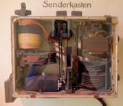
We were in the „Morse-Übungs-Raum“ (Morse Code Practice Room) when a wooden box
with some knobs caught my eye. The top cover was removed, some old coils were visible
and an inscription said „Senderkasten ( Transmitter Box).
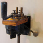
Next to this was a Morse key with a big handle, an antenna roll and a round shaped
voltage transformer.
It was a kind of aircraft transmitter, but no receiver was shown, also it was not possible to
identify the manufacturer. I decided to investigate further about the purpose of this
wooden „Senderkasten“. Within two days after my request I have received reply from the
“Deutsches Museum” in München and also Werner Thote DL1VHF, sent some interesting
material about the unit and radio telegraphy in the First World War.
With this information, it became clear that the exhibit shows the aircraft transmitter
„AFS 35 “ made by Telefunken and the necessary equipment built into the aircraft.
This configuration as “transmitter only” was used from February 1915 until November
1916 when the AFS 35 – Rev. D, now a transceiver, was introduced in the German Air
Forces.
The development and usage of wireless radio communication in aircrafts at the outbreak
of the First World War was still in its infancy. Some experiments about air-ground/ground-
air communication were made, but did not meet the requirements of the military
authorities and were not suitable for mass production into aircrafts.
The primary need for a reliable air to ground communication came from the artillery troops
as it was mandatory to know how accurate the gunners were shooting at the enemy lines.
This often caused heavy death toll by friendly fire and led to the introduction of the so
called “Artillerie Flieger” (artillery pilot) at the infantry troops. Initial attempts were made to
signal via special flight patterns how accurate the artillery was, but this took a long time
and was inaccurate, too. Next attempts were made to signal with flare guns, but these
often did not light up properly, visibility was limited and impossible to see in foggy weather.
Also drop bags with reports did not bring successful results as they were blown away by
the wind, got stuck in trees or could not be found at all.
Finally the military authorities realized that only via the usage of wireless transmission in
aircrafts and reliable equipment a proper feedback about the artillery accuracy could be
given.
This sped up the development of aircraft transmitters and the need of using an observer in
the backseat being capable of transmitting Morse Code messages to the ground.
The company „TELEFUNKEN“ had already recognized the importance of wireless
communication and was very skilled in manufacturing and selling wireless equipment. No
wonder they started selling their products to the military already from April 1912. These
Telefunken transmitters were firstly used for short range aerial communication, were
battery operated and used to verify the accuracy of the artillery. For surveillance flights
with the need for long range communication the transmitter later got its power via an
AC/DC power generator connected to the aircraft engine or propeller driven.
Interestingly during my research I got hold of a copy of TELEFUNKENs catalogue of
wireless equipment, which was translated already into 4 languages (German, English,
French and Spanish). Advertised in this catalogue were wave meters for different
wavelengths from 75m to 15.000m, intensity meters for telephones and detector testers
for telephones. Also transmitters up to 5watts, receivers and receiver test equipment were
in the product portfolio during these days.
The development activities and success of TELEFUNKEN finally lead to the development
of the AFS 35 and its usage in infantry planes, mainly “Rumpler C-Typen” (Rumpler
aircraft Type C).
The aircraft configuration consisted out of the following components:
The AFS35 transmitter and ampere meter
Antenna wheel with a retractable wire antenna
Morse key or automatic character generator (easy feedback about artillery
accuracy)
AC/DC power generators(up to 250W AC)
The AFS 35 Transmitter:
The AFS35 transmitter was introduced in February 2015 and was the first real battlefield
usable transmitter.
Dimensions were 33.5cm in length, 25.5cm in width and 14.5cm depth; it weighed about
8.62kg and could transmit on three wavelengths (150m, 200m and 250m) which was
unique to its predecessors being able to transmit only on one wavelength.
Also it was possible to select two different transmit power levels. The total production
volume of was about 1,600 units.
On the front panel you find 3 knobs for choosing the output power (a), wavelength (b) and
on the right hand side the tuning knob/variometer (c) to match the wire antenna according
to its length.
On the right hand side, next to the tuning knob is the connection for the wire antenna (g),
at the bottom of the right hand side is the power connector and Morse key connector (v).
On the left hand side you find the connection to the counterpoise of the antenna (r).
Circuit Description:
In principle the AFS35 consists of four elements:
Gleichstrom-Kreis (DC circuit)
Wechselstrom-Kreis (AC circuit)
Stoss-Kreis (closed, gradually adjustable resonant circuit)
Luftdraht-Kreis (Antenna circuit with open, adjustable circuit)
The main parts of the electric circuit are the transformer, capacitor, spark gap and a
variometer.
Additionally via switch I it is possible to select different output levels via switching a
resistor into the DC circuit and reducing the capacity of the spark gap. Switch L was used
to select the wavelength by in-/decreasing the inductance of self-induction coil (SO).The
observer in the back seat adjusts the circuit via the tuning knob/variometer for maximum
antenna current as indicated on the ampere meter.
The antenna:
The antenna was made of copper wire, with a length of 40m and thickness of 1mm. The
observer in the back seat reeled off the antenna plus counterpoise. At the aircrafts
cruising speed of 150km/h it was dragged horizontally behind the aircraft.
I would like to thank the following persons for the information and help in writing this
article:
Manfred Bauriedel, DK4NQ; Hans Holzer, Dt. Museum München; Thomas Höppe, DJ5RE;
Werner Thote, DL1VHF
Literature:
- Link Dt. Museum München: http://www.deutsches-museum.de/en/flugwerft/information/)
1.
Telefunken Zeitung , Nr. 16, July 1919
2.
-Telefunken Buch, Teil 2-7, 1919
3.
-Die Funkentelegraphie in den Fliegerverbänden – Teil 3; Berlin August 1916
4.
-Flugsport 1918, No. 6 – Seite 128 – 138
5.
-Illustrierte Flugwelt, 1. Jahrgang 1919 Seite 408 – 413
6.
-Funkentelegraphie für Flugzeuge von OLt. Erich Niemann; Berlin 1921


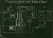
Schematic diagram of the
“Flugzeugsender Telefunken”
– Aircraft transmitter
by Telefunken;
Source: Dt. Museum
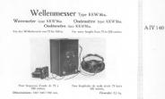
Telefunken book from 1919
(Sales literature)
Source -2 :Sample picture of the
Telefunken Sales catalogue;
Telefunken Buch, provided by
Manfred Bauriedl
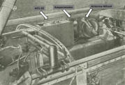
Installation example of AFS-35
Transmitter, ampere meter
and antenna wheel.
Source -3:
Die Funkentelegraphie
bei den Fliegerverbänden
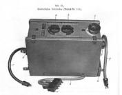
Source -3: AFS 35 Top View
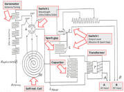
Source -4: Flugsport 1918